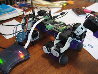
Ok, it's been quite some time since progress on PEDRO the robot dog was posted, but since we've just had our first kid (welcome little baby Emily!), I think I can be forgiven...

There's been quite a bit of development behind the scenes of Pedro - but about the only visible change is much smoother walking due to improving the controlling windows software running on Microsoft Robotics Studio.

The robot has always been plagued by really bad timing jitter due to the use of windows software to generate servo movements at 50Hz; precise timing is just not a strong point of windows software in general.

I did a lot of experimenting with different methods of generating timing, and settled on the windows multimedia timer as the best method to use to generate the 50Hz servo update messages that get sent to the robot. I then had a lot of trouble getting them to work within my Robotics Studio code for some reason. I won't bore you with the details, but I got some help on the MSDN robotics forum from KuSter (follow this thread if you're interested) and ended up writing a little separate program to act as a metronome using the MM timers and sending TCP/IP timing messages through to the robotics studio service every 20ms. Eventually I'm going to change the software around quite a bit, and have the robot ask for position updates from the PC every cycle so the robot becomes the timing master rather than just a slave device. This way the AVR micro can precisely control the rate position updates are sent to the servos.

In the meantime still generating regular servo updates from the PC end, the timing is much better (still far from perfect though); check out this video -


In the video I'm using a USB cable for communications between the robot and the laptop because I still have a problem with the WiFi connection to the robot. The WiFi is provided by a Lantronix WiPort module (same as the Surveyor folks) but I've had problems with getting consistent performance from it given I'm trying to send servo updates at 50Hz across the WiFi link.

I'm also tackling the WiFi problem as well - I've just bought a replacement WiFi module from the guys at SparkFun, it's the WiFly GSX module from Roving Networks. I bought the module already mounted onto a breakout board so I could test it right away.


I also got this FTDI 3.3V USB converter from SparkFun as well so I could hook it up to the new WiFi module and start testing it right away. This I did, and it worked without any trouble at all. I tested it by hammering it with 50Hz packets (actually I used my normal Pedro robot software to be totally authentic), and it worked very well without any of the strange dropouts I got with the Lantronix WiPort module. Of course it is possible that my Lantronix module is a dud, but regardless the WiFly GSX is lower power, smaller and just as fast, so if Pedro gets a revision 2 of the controller PCB, the WiFly will get pride of place. In the mean time, I will remove the Lantronix module and mount the WiFly onto the current board as neatly as possible.

Other than the stuff I've described above, I've been tooling away on the walking algorithm in order to finally have a system that can calculate and plan the foot movements dynamically, so the robot stays stable and upright no matter what direction or rotation it is instructed to follow. I've come a long way with this, but it'll need some serious debugging and testing before its ready for prime time.

"PEDRO" the quadruped robot got a lithium polymer battery last week courtesy of eBay. I had been putting off buying a heavy and expensive large capacity LiPo battery until I had got the walking algorithms working a bit better and I could truly test the ability of the robot to take the 500g or so of a heavy battery, but now batteries are available on eBay for not as much money, I just took the plunge and bought a 3000mAh 3 cell battery pack and charger for the robot.


The battery weighs just 215g, and cost approx AU$50 delivered. The charger can charge up to 5A and will do a balance charge, monitoring individual cell voltages.

Next I had to fit it to the robot, as the original design called for a larger pack slung underneath the body and neatly held in by the spacers between the side plates. The new smaller pack needed some extra holes and some plastic brackets to hold it in;


Once the battery was on and tested ok, I had to return to the firmware for the AVR micro and write some code to support turning the unit on and off via the onboard mosfet and soft on/off button. Also needed was some code to talk to the ADC chip on board which has the battery cell voltages on it, so I could implement low battery automatic cut out and (hopefully soon) viewing of the battery level remotely over the wifi link. Of course it didn't go smoothly...


Once again the usb logic analyser came in very handy in debugging the SPI comms between the micro and the AD7490 chip (16 channel, 12 bit converter). You can also see the JTAG MkII from Atmel connected (expensive gadget, but very handy for debugging AVR code).

I've also been working on the walking algorithms, and various other software and hardware bits and pieces such as improving the communications (the WiPort wifi module doesn't seem to work as well as I'd hoped - it needs really good signal strength or every now and again it will drop out for up to a second or so). Once I've got some of these wrinkles smoothed out and the walking nice and smooth I'll post some more video.

Finally "PEDRO" the quadruped robot has taken it's first steps outside of simulation... Admittedly it suffers from the shakes and falls over continually, but it is still a milestone.

I finished the Microsoft Robotics Studio control service to the point where it can send out regular servo position updates over the wifi link to the robot, taking direction from the quadruped differential drive service which implements the walking algorithm.

Here's a short video of the shaky movements;


Obviously there is a lot to improve upon. The balance and stability control aspects of the software, although they worked ok in the simulation environment, are obviously not working too well on the physical robot. I will definitely improve these, but I'm more worried at the moment about making the servo movements a lot more smooth than they are now.

I was initially sending servo position and speed updates (via a SYNC WRITE command on the dynamixel network to the AX-12 servos) at only 10Hz, and the first thing I tried was increasing the rate of updates. Even increasing the rate to 50Hz or even 100Hz didn't improve things much. I also removed the speed control code and used a AX-12 speed register setting of zero which represents maximum speed with not much effect. A quick look at the AX-12 data stream using the completely cool and now indispensable logic analyser showed the root cause of the problem - relatively large amounts of jitter in the timing of the AX-12 packets.

So next I'll be working on improving this aspect so the robot can have smooth movements. Although some people have managed to cram inverse kinematics and other trig type calculations into Atmel AVR micros similar to those on the PEDRO robot, I think I would rather keep the robot platform as independent from the control methodology as possible to allow for completely novel approaches to be implemented on desktop computers and quickly tested. So step one will be to use more accurate timing within the Microsoft Robotics Studio code. Rather than use the TimeoutPort mechanism provided which according to online sources can have 16-20ms jitter (apparently improved in MRDS 2.0) I will use change the code to use timing based on the multimedia timer which should give much more accurate results.

Mind you I expect this will only be step 1, because there are many sources of varying latency in my robot system - wifi, processing delays on board the robot, SPI comms between the main micro and the AVR handling the servo comms etc. So I am thinking I might put a queuing system onto the AVR which handles the servo comms, and rather than just passing data onto the servo bus as soon as it is received, I might actually decode the AX-12 packets and buffer them so I can resend them out at precise intervals. If the buffer holds only a few packets then the delay between the PC end and the actual robot movement won't be that great (maybe 100ms?). I will have to make the rate that the packets are taken from the buffer and sent out to the AX servo bus adjustable with a long term average, so that the micro can tolerate timing differences between the PC end and the micro. For example if the PC end is sending out packets on an average interval of 20.4ms and the micro expects packets at exactly 20ms and is taking packets out of the queue at that rate, then the queue will eventually empty. If the micro measures the average arrival timing of the incoming packets and adjusts its interrupt driven timer for precisely sending out packets accordingly, then the buffer will stay more or less at its intended size.

I thought I would post some info on some of the work that has gone into making the quadruped robot "PEDRO" walk in Microsoft Robotics Studio simulation environment.

Here's a video which briefly shows the latest hardware progress before moving on to demonstrations of some elements of the control software. The robot hardware and onboard firmware is now basically ready - though as you can see in the video I'm only up to manually moving one joint at a time until some more PC end software is written.


The control software is written in C# and implemented as robotics studio services. Using Microsoft Robotics Studio has allowed the control software to be tested out on a simulated robot before being let loose on the real nuts and bolts hardware. It is amazing how often a simple software bug seemed to make the simulated robot do complicated yoga poses that I'm sure would have led to stripped gears on the real bot...

The most important element of the control software is the inverse kinematics routines. These take a foot position vector relative to the robot body and work out the necessary joint angles to put the foot into that position. Once this important function is in place, you can then make a leg step simply by moving the foot position through the desired curve, and the leg joint angles are all taken care of by the inverse kinematics.

After the inverse kinematics was working well, the next step was simply adding some other ways to set the foot positions by setting a body movement relative to the ground. Although this sounds complicated, to move the body forward relative to the ground, for example, all you have to do is adjust all the feet position vectors backwards a bit, and again, the inverse kinematics takes care of the rest. Body rotation is handled much the same way; a method is provided to rotate the body which actually rotates the four feet position vectors (or however many feet are actually on the ground at the time) around the body centre.

The actual stepping motion is created by choosing a target for the foot position using the current movement direction and current desired body rotation. The path the foot follows during the step is an elliptical one so that the foot moves almost directly straight up off the ground at the onset of the step motion and similarly comes down at footfall almost vertically. This should help in clearing obstacles (or carpet etc.). Once the target foot position is chosen and the step is started, the software updates the foot position and servo rotation speed using the calculated path every iteration. Meanwhile the other three non-stepping legs are being moved by the body motion functions - ie. every iteration the body stance is shifted in the desired movement direction.

Another important component of the control software is the methods I have added for calculating the robot's current centre of mass. This is calculated using the known current position of all the joints and the mass of each segment. It is important to know the centre of mass in static walking so that stability can be maintained by shifting the body pose before a foot is lifted off the ground. For example if a particular foot is selected as the next to step, then the body centre of mass should be compared with a triangle formed by the other feet. If the centre of mass falls vertically within the triangle, then the robot will be stable with that foot lifted off the ground. If not, then the body stance can be shifted before the step is started so that the centre of mass falls within the stability triangle.

The step order is most critical for stable walking, and I found that for forward motion, stepping the rear then front leg on one side followed by the rear then front leg on the other side resulted in the best stability. Currently PEDRO's walking algorithm adapts this basic pattern for whichever quadrant the desired direction of travel falls in. For example if the desired direction is pretty much side stepping to the right, then the best foot step order will be front left, then front right, then rear left then rear right. I have also worked in the desired rotation into the algorithm which picks the next foot to step, and if the desired rotation is more dominant than the translation movement, then the best order for rotation takes over which is stepping around the clock ie. if rotating clockwise, then step front left, front right, rear right, rear left.

This method is working quite well in practice, however I would like to replace it with something a little less scripted. I did try choosing the next foot to step based on which foot could possibly step the furthest in the desired direction, however this wasn't particular successful. I won't do any further work on this right now however, because it will be far more exciting to test out the walking algorithms as they are with the real robot, and this is hopefully not too far off. I have to finish the software service which communicates with the robot using tcp/ip, passing on the joint movement messages to the onboard controller. With a bit of luck the real robot will walk just as successfully as the simulated one, but I'm tipping there will be problems to solve...

Recently I bought a wireless Xbox controller purely for use with Microsoft Robotics Studio, to remote control the PEDRO quadruped robot and steer it around the floor. To get to this pretty simple goal, a lot of steps are needed - I already had a simulation of the robot going in Robotics Studio, and even walking, but in a very 'canned' sequenced fashion, with all the joint angles moving between key frames that are hard coded. See this blog post for a video of the rather unsteady robot simulation walking in a straight line. This method won't do if you want to control the robot in an unplanned fashion where the direction and speed of walking are able to change at any time, so a more sophisticated approach is needed.

Since then I have written several robotics studio services to support the robot. One communicates with the real physical robot (still in progress), another controls the simulated robot. These two implement the same 'generic contract' as robotics studio terms it, so other services can be built to interchangeably communicate with either the real or simulated robot without any recompilation. A third robotics studio service implements the 'generic differential drive' contract so that it can accept differential drive control signals from other services which use this contract. This service contains all the software which implements the new walking algorithm capable of rotation, walking in any direction and varying the speed of the robot. The output of this service is essentially a continuous set of joint angles which can get sent to either the real robot control service or the simulation robot service.

The beauty of allowing the walking service to accept differential drive control signals (also called skid steering) is that potentially many different services can be connected up to control PEDRO, even though the original authors of the services have not even seen the robot. The drawback is that there is not much control with just a left and right motor speed signal for a 14 degree of freedom quadruped robot! However I will allow more complicated forms of control in the software which will work with services I create, as well as the more standard differential drive control. Another cool little side benefit is that the standard dashboard service supplied with robotics studio accepts input from the mouse or game controllers like the wireless Xbox controller and so can be used to remote control your robot with a convenient wireless handheld device. Because of this, I had to buy one to try it out!


I'm still working on a video which describes the technical detail behind the actual walking algorithms, and I'll post it when its done. Of course making the robot walk in simulation, and making the real robot actually walk across your floor might be two very different things - and this is something I'll hopefully find out pretty soon as the hardware has progressed really well.

The physical robot is now fully wired up with all the AX-12 servos connected up to the onboard controller which is communicating over WiFi quite well. I can manually drag a slider up and down and move individual joints one at a time using a slightly modified version of Scott Ferguson's DynaCommander software. I haven't fitted any battery to the robot yet, so it is still tethered to a power supply, because I would like to put a dummy weight equal to the battery weight (nearly half a kilogram for the one I want to use) onto the robot to make sure it can lift and carry this weight comfortably. This way if the robot can't in practice support the heavy battery I can still source and fit a lighter battery option with less run time.

I'm currently working on the service which will replace the simulation and communicate with the real robot. When that's tested and debugged it will be really interesting to see if the walking software that works so well in simulation can work as well in reality!